Website Design Copyright 2026 © HONEST SENSOR CORP.
All Rights Reserved. 網頁設計 by 覺醒設計
CATALOG TYPE
Product Categories
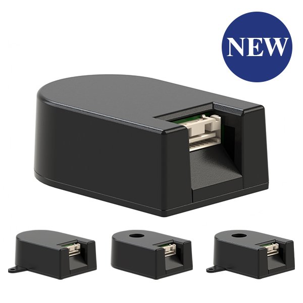
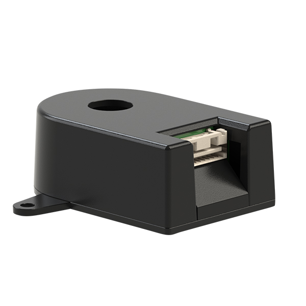
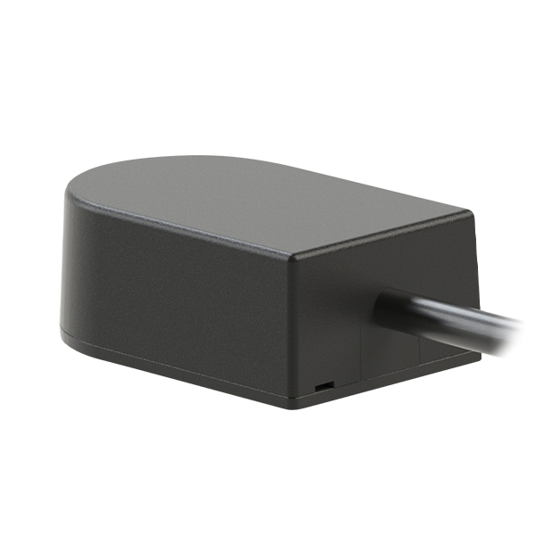
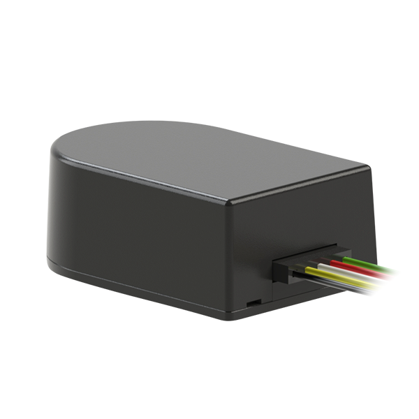
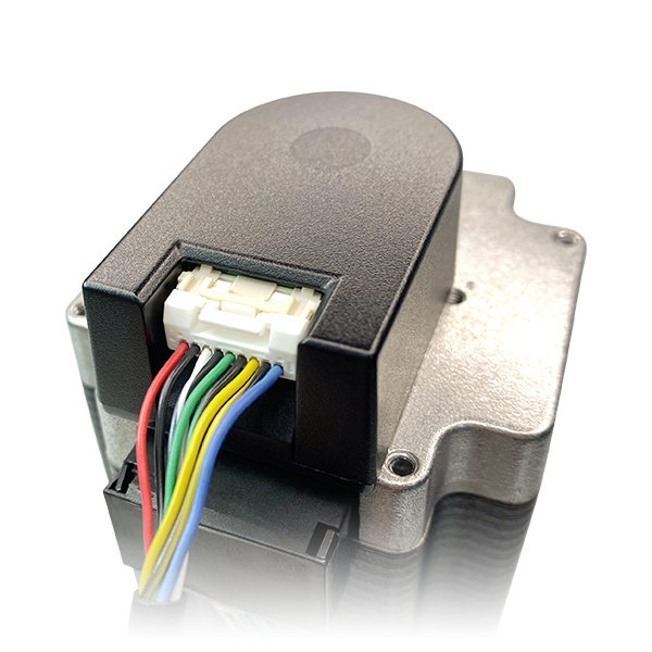
Model Encoder Modules_Incremental
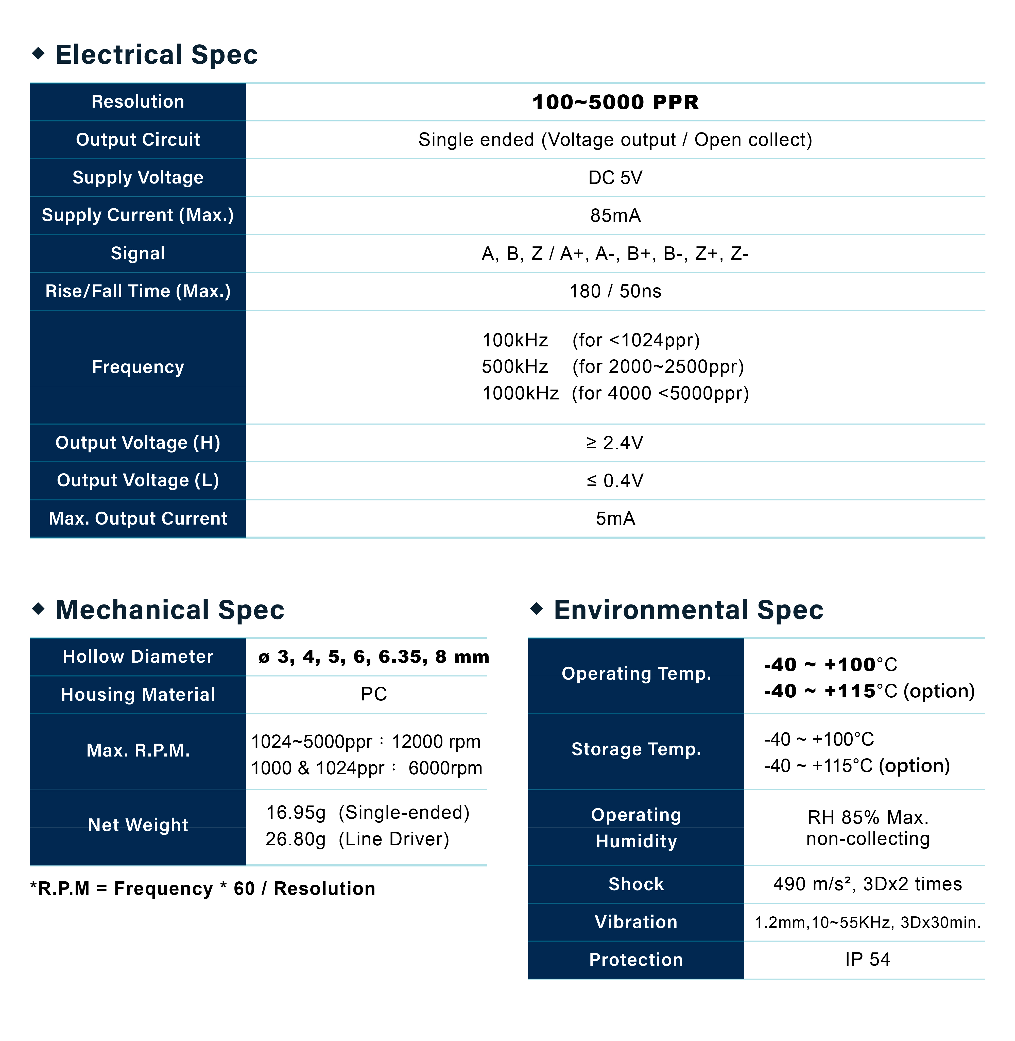
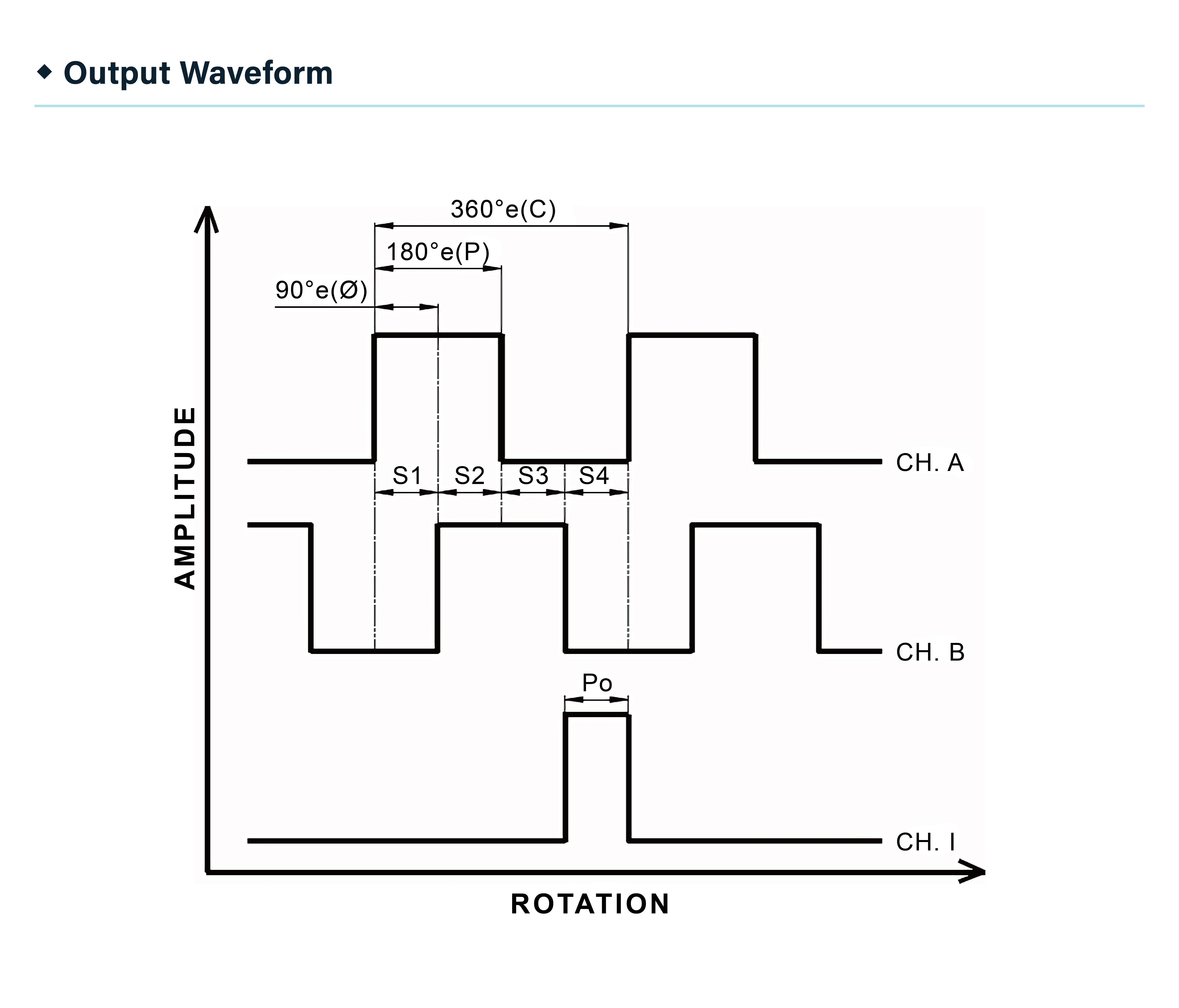
100~5000 PPR │ ABZ signal
Product Description
Resolution :
Hollow :
Output circuit :
Ba
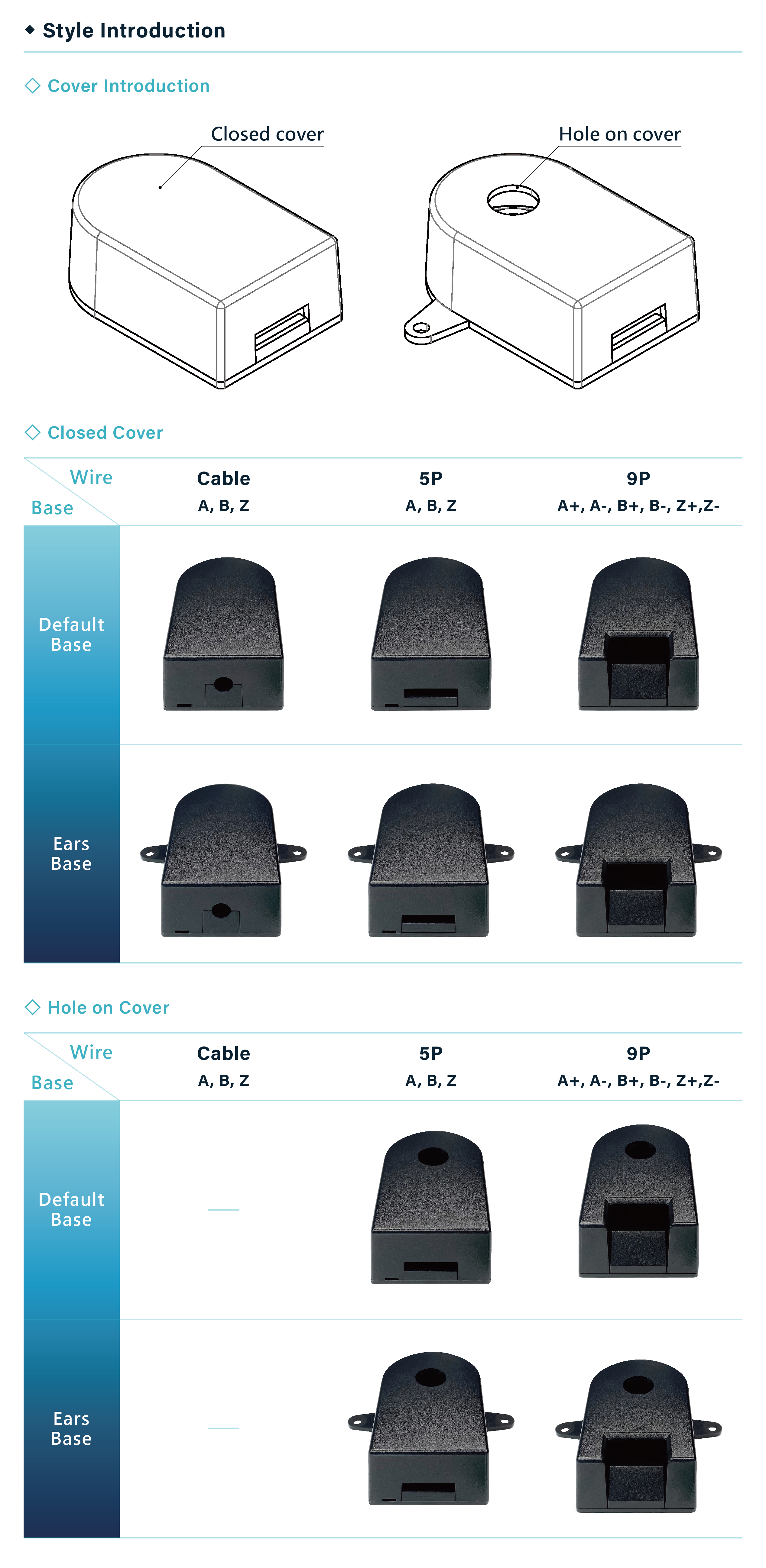
Cover :
Tem. :
Installation tool :
Quantity:
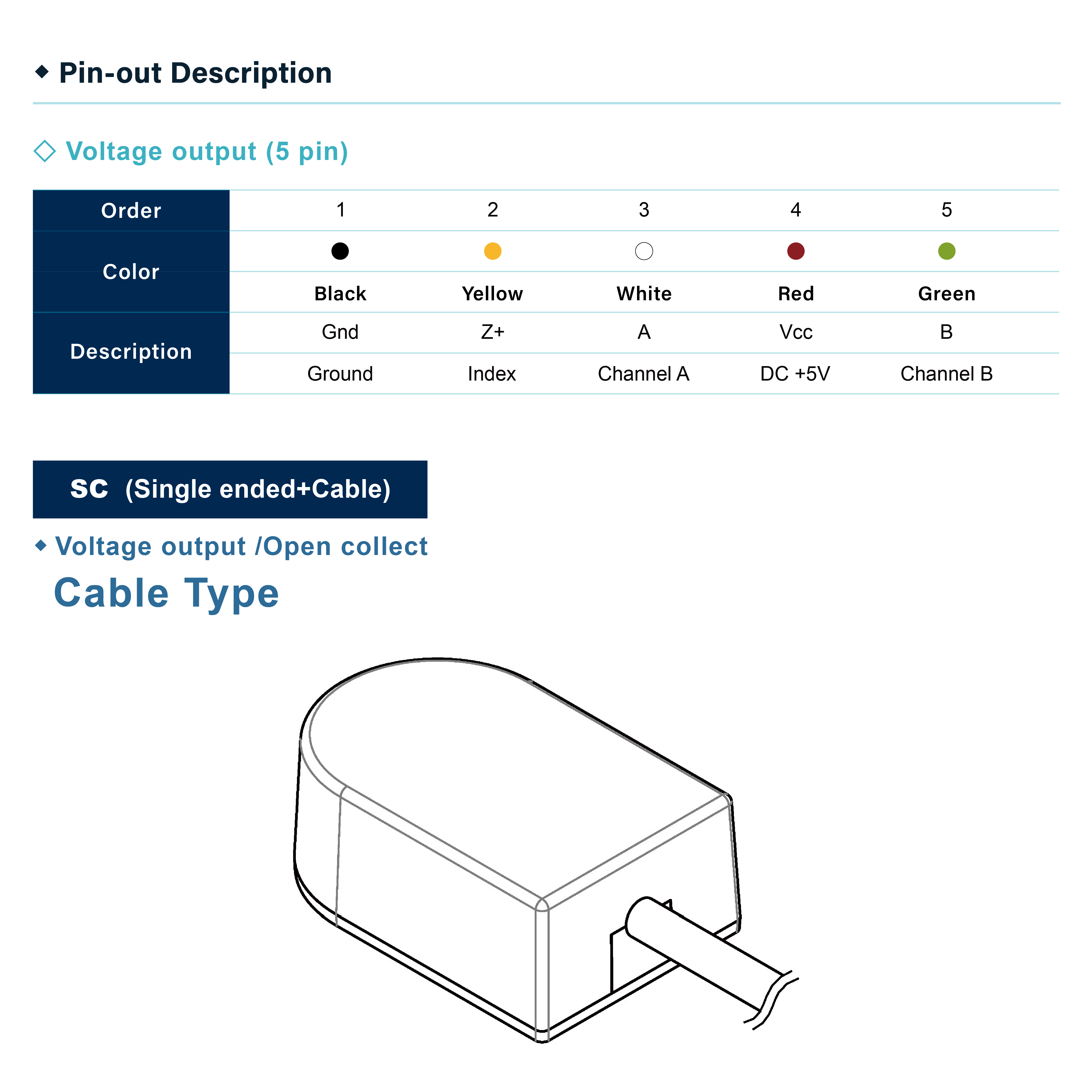
Cable length
500mm
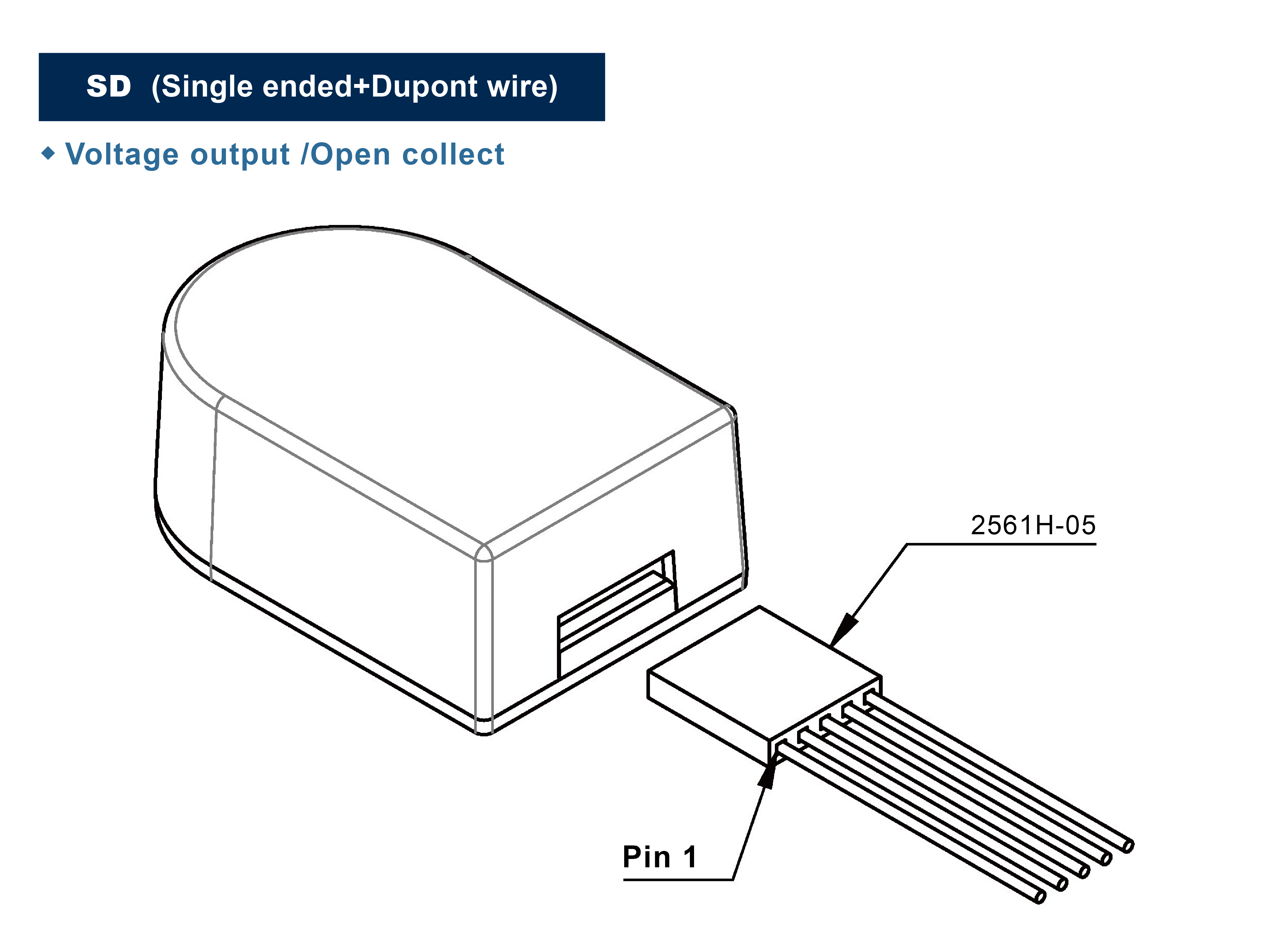
Cable length
150mm
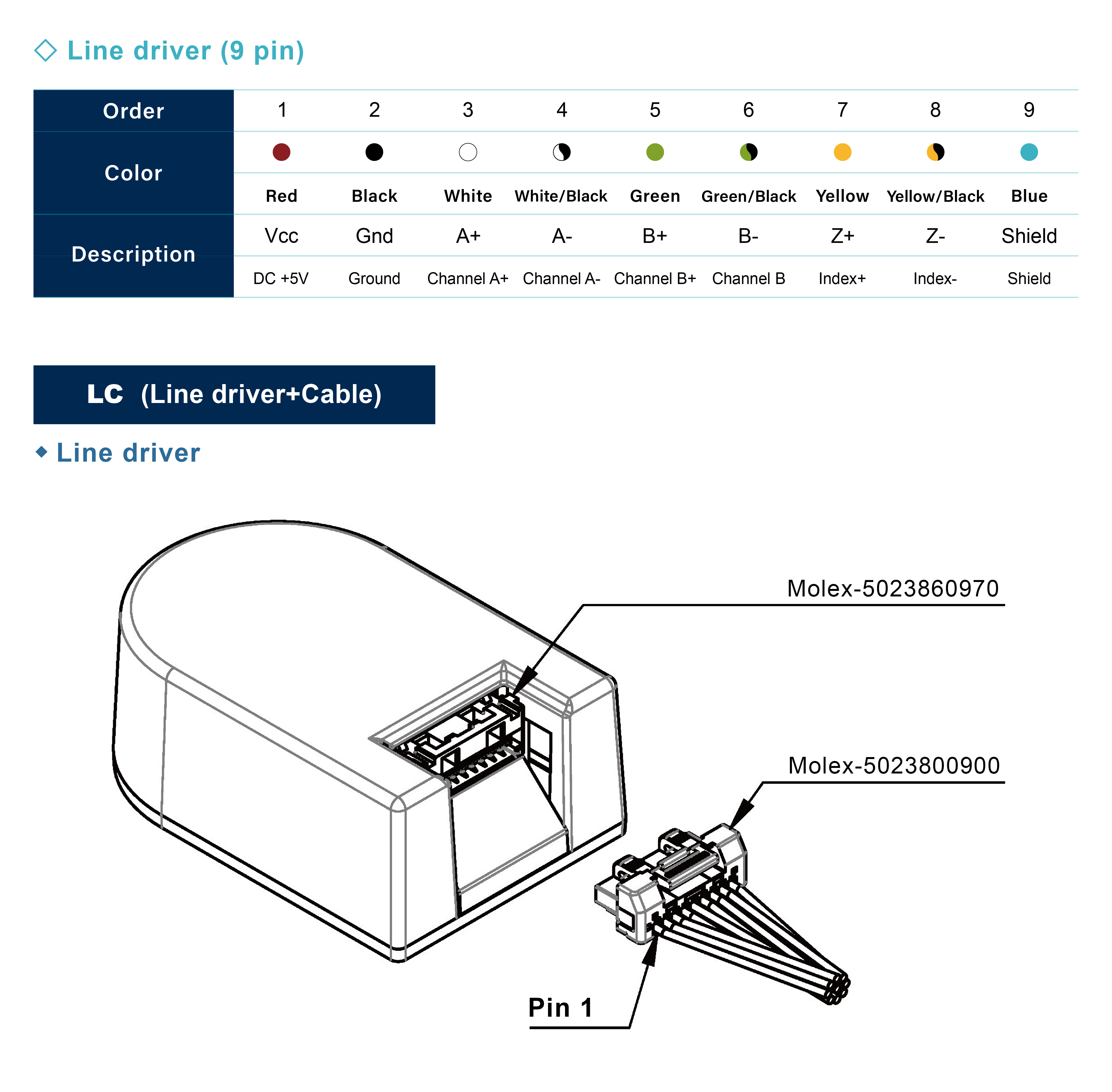
Cable length
500mm
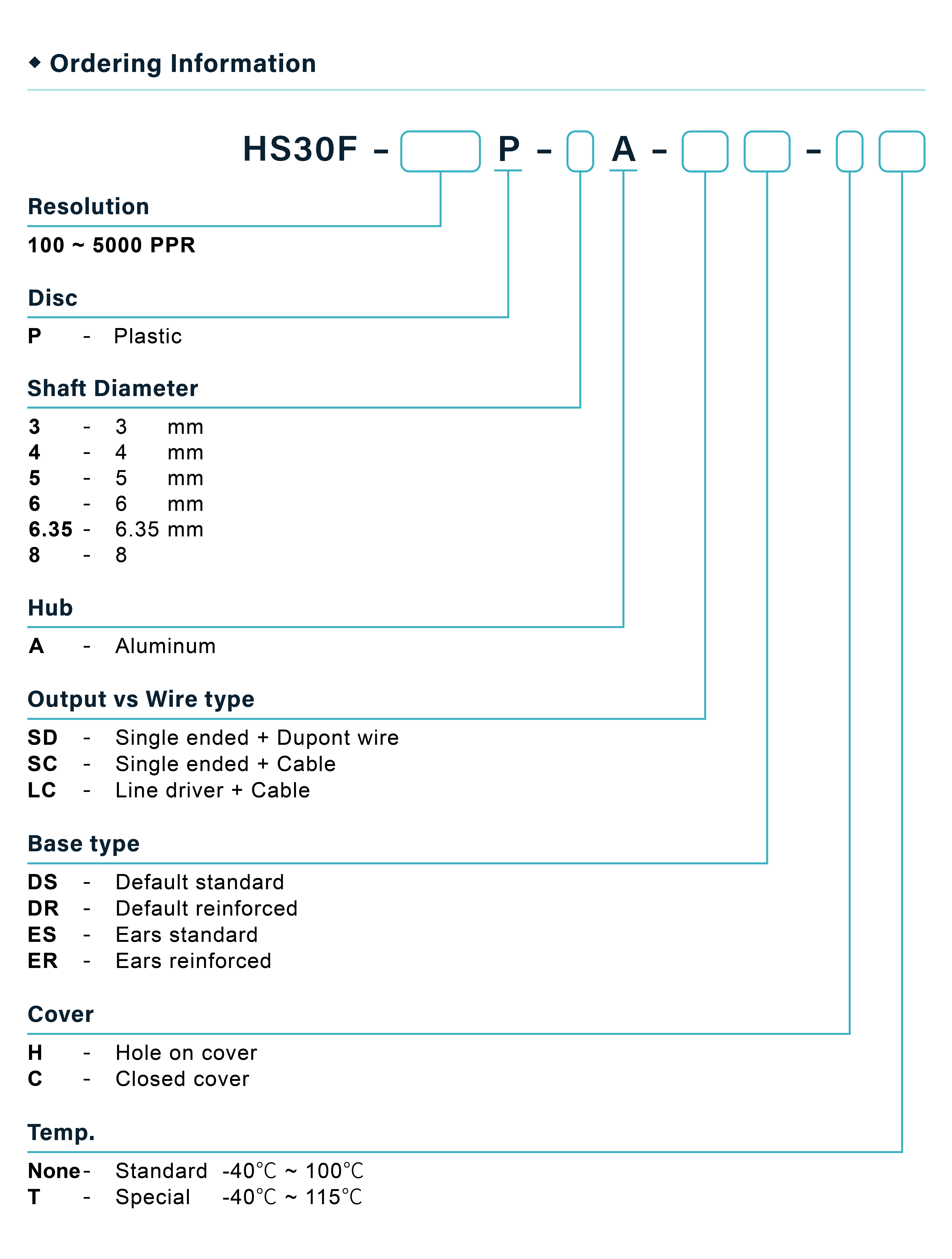
※ Single ended = Voltage out / Open collect
※ High Temp. version (115℃) only for ≥ 1000 PPR.
※ SC (Single ended+Cable) - Cable :Top cover without holes
Parts List
A. Cover x1
B. Base x1
C. Screws - Long x2
D. Screws - Short x2
E. Sensor x2
F. Hubdisk x1
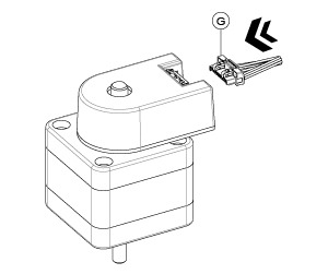
G. Cable x1
Installation Tool
H. Centering tool x1
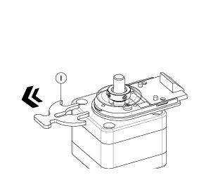
I. Space tool x1
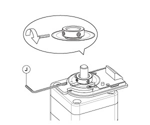
J. Hex wrench x1
Assembly Instructions :
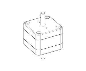
Prepare the motor.
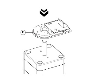
The Ⓑencoder base is mounted on top of the motor.
Place the Ⓗ centering tool onto the shaft.
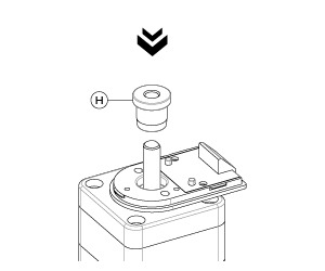
Tighten the mounting Ⓓscrews.
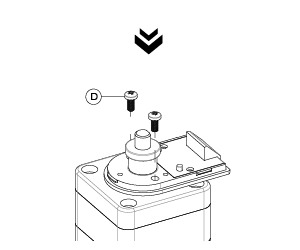
Remove the Ⓗcentering tool.
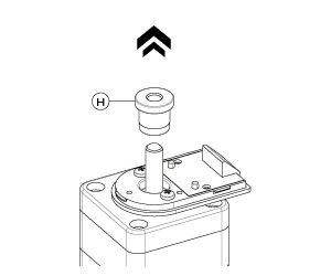
Place the Ⓘspace tool.
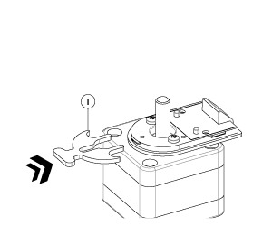
With the code-disk facing downwards,
install the Ⓕhubdisk onto the shaft.
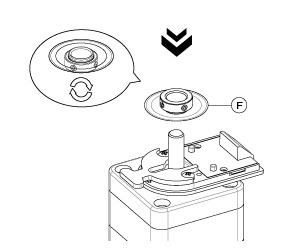
Tighten the set screws of the hubdisk.
Remove the Ⓘspacing tool.
Place the Ⓔsensor onto the base gently.
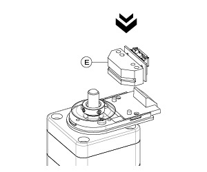
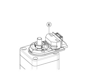
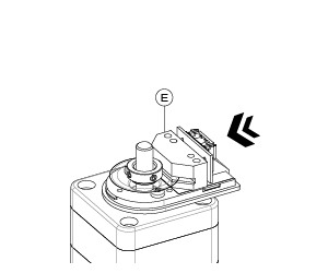
Push the Ⓔsensor forward.
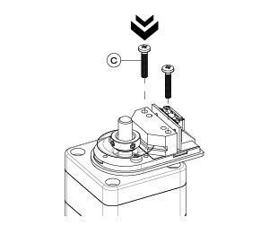
Fasten the sensor with the Ⓒscrews.
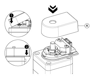
Close the Ⓐcover by sequence.
Assemble the cable.
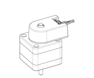
The assembly process is now completed.
DOWNLOAD
HS30F_SpecificationsDOWNLOAD
HS30F_3D models_standardDOWNLOAD
HS30F_3D model_reinforcedDOWNLOAD
HS30F_Assembly Guide
Cable length
500mm
Cable length
150mm
Cable length
500mm
※ Single ended = Voltage out / Open collect
※ High Temp. version (115℃) only for ≥ 1000 PPR.
※ SC (Single ended+Cable) - Cable :Top cover without holes
Parts List
A. Cover x1
B. Base x1
C. Screws - Long x2
D. Screws - Short x2
E. Sensor x2
F. Hubdisk x1
G. Cable x1
Installation Tool
H. Centering tool x1
I. Space tool x1
J. Hex wrench x1
Assembly Instructions :
Prepare the motor.
The Ⓑencoder base is mounted on top of the motor.
Place the Ⓗ centering tool onto the shaft.
Tighten the mounting Ⓓscrews.
Remove the Ⓗcentering tool.
Place the Ⓘspace tool.
With the code-disk facing downwards,
install the Ⓕhubdisk onto the shaft.
Tighten the set screws of the hubdisk.
Remove the Ⓘspacing tool.
Place the Ⓔsensor onto the base gently.
Push the Ⓔsensor forward.
Fasten the sensor with the Ⓒscrews.
Close the Ⓐcover by sequence.
Assemble the cable.
The assembly process is now completed.
DOWNLOAD
HS30F_SpecificationsDOWNLOAD
HS30F_3D models_standardDOWNLOAD
HS30F_3D model_reinforcedDOWNLOAD
HS30F_Assembly GuideIn compliance with EU personal data protection laws, we are committed to protecting and providing you with control over your personal data. By clicking "Accept All", you allow us to place cookies to enhance your experience on this site, help us analyze site performance and usage, and enable us to deliver relevant marketing content. You can manage your cookie settings below. By clicking "Agree" you agree to the current settings. For more information, please visit the Privacy Statement.
This website uses cookies
In compliance with EU personal data protection laws, we are committed to protecting your personal data and providing you with control over it. By clicking "Agree", you allow us to place cookies to improve your experience on this site, help us analyze site performance and usage, and allow us to deliver relevant marketing content.
By clicking "Only necessary" you allow us to place only necessary cookies. The website cannot function without these cookies and you cannot switch them off on your system. These cookies are typically set only in response to an action you perform (i.e. a service request), such as setting privacy preferences, logging in, or filling in a form. You can set your browser to block or prompt you for these cookies, but this may prevent some site features from working.